To improve the life of triac, the spike arrester circuit built around resistor R9, metal oxide varistor MOV1 and capacitor C7 is used. This triggers the main triac BT139 and the AC supply for the load becomes available across connector CON2.

High state at Q9 makes MOC3041 to conduct. The current high output states of 4017B remain high till the power is off. This stops the counting process in 4017B. When Q9 goes high with tenth pulse, CLK EN also goes high. Each output of 4017B goes high one by one after each clock pulse. You can change the delay time (0.1 to 1-sec) of this circuit by varying VR1.ĭuring power-on, clock enable pin 13 (CLK EN) and pin 11 (Q9) of 4017B are in low states. Resistor R2, capacitor C5 and preset VR1 are timing components for NE555 IC. Optotriac has the advantage of triggering 230V AC power by itself and providing circuit isolation.ĭC power for this circuit is derived from step-down transformer X1, bridge rectifier BR1 and capacitors C3 and C4. The triac is triggered by optotriac MOC3041 (IC3). The optimum load will be 220V×9.6A=2112 watts. The maximum 16-ampere current means we can have 60 per cent as optimum current, that is, up to 9.6 amperes (or 16×0.6=9.6 amperes). The output is built around triac BT139, which can switch up to 16-ampere AC load. Output pin 11 (Q9) of 4017B goes high at 10th pulse received from NE555. As a result, 4017B gets breezed and its ten outputs (Q0 through Q9) become high sequentially. The output pulses from NE555 are fed to clock input pin 14 of 4017B. When the main power is switched on, 4017B starts counting the pulses received from NE555. VR1 preset is used to vary the timings from 0.1-sec to 1-sec pulse in NE555 IC. NE555 IC is used as a bistable oscillator. The "on" time for the output to turn on the relay would be from 500 milliseconds to 30.Timing accuracy is achieved by using decade counter 4017B. The time after the button release would be from 250 milliseconds to 5 seconds. The sequence would not restart until the button was pressed and released again. I will need an adjustable time delay (possibly displayed time) after the switch is released, then the output would go on for an adjustable time (also possibly displayed) before shutting off.
SIMPLE DELAY TIMER MANUAL
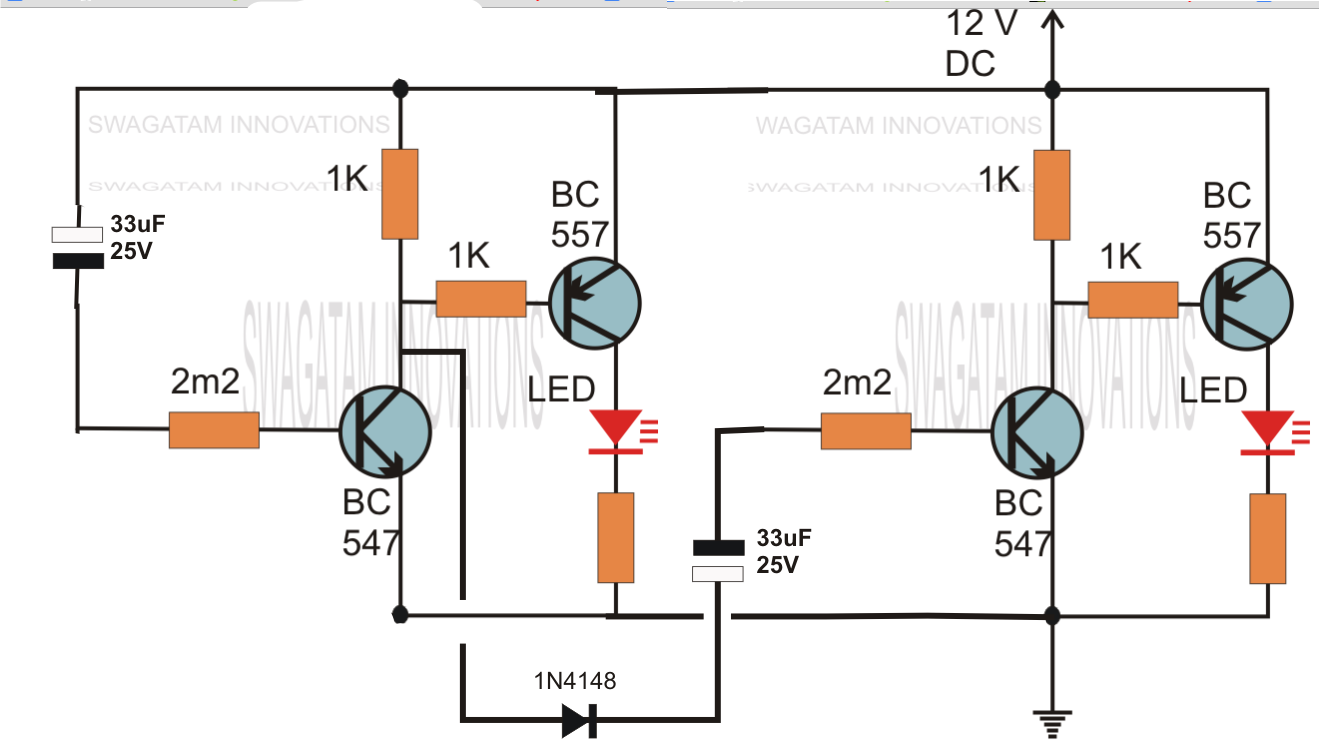
This would be done in 12V and the sequence will be initiated by a manual switch. "I am looking to build a circuit that would control an output relay. This circuit was requested by one of the avid readers of this blog, Mr. The above circuit can be modified to produce a two step sequential delay generator.

The addition of another transistor stage increases the sensitivity of the circuit, which enables the use of larger values of the timing resistor thereby enhancing the time delay range of the circuit. Along with the capacitor, the value of the base resistor also plays an important role in determining the timing for which the transistor remains switched ON after the push button is released. On releasing the push button, though the power to the base gets disconnected, the transistor continues to conduct with the aid of the stored energy in the capacitor which now starts discharging its stored charge via the transistor. Resistor and switches ON the transistor and subsequently the LED. Telephone Circuits ▼ Telephone Circuits.Converter Circuits ▼ Converter Circuits.Oscillator Circuits ▼ Oscillator Circuits.


 0 kommentar(er)
